 PONKA
Indirect air-to-liquid heat recovery
Transfer exhaust heat through a heat exchanger into a separate liquid circuit for a suitable heating duty.
ExploreHeat recovery / PFD-14
Recover heat from a suitable exhaust stream into water where direct contact and a useful water-heating demand are compatible.
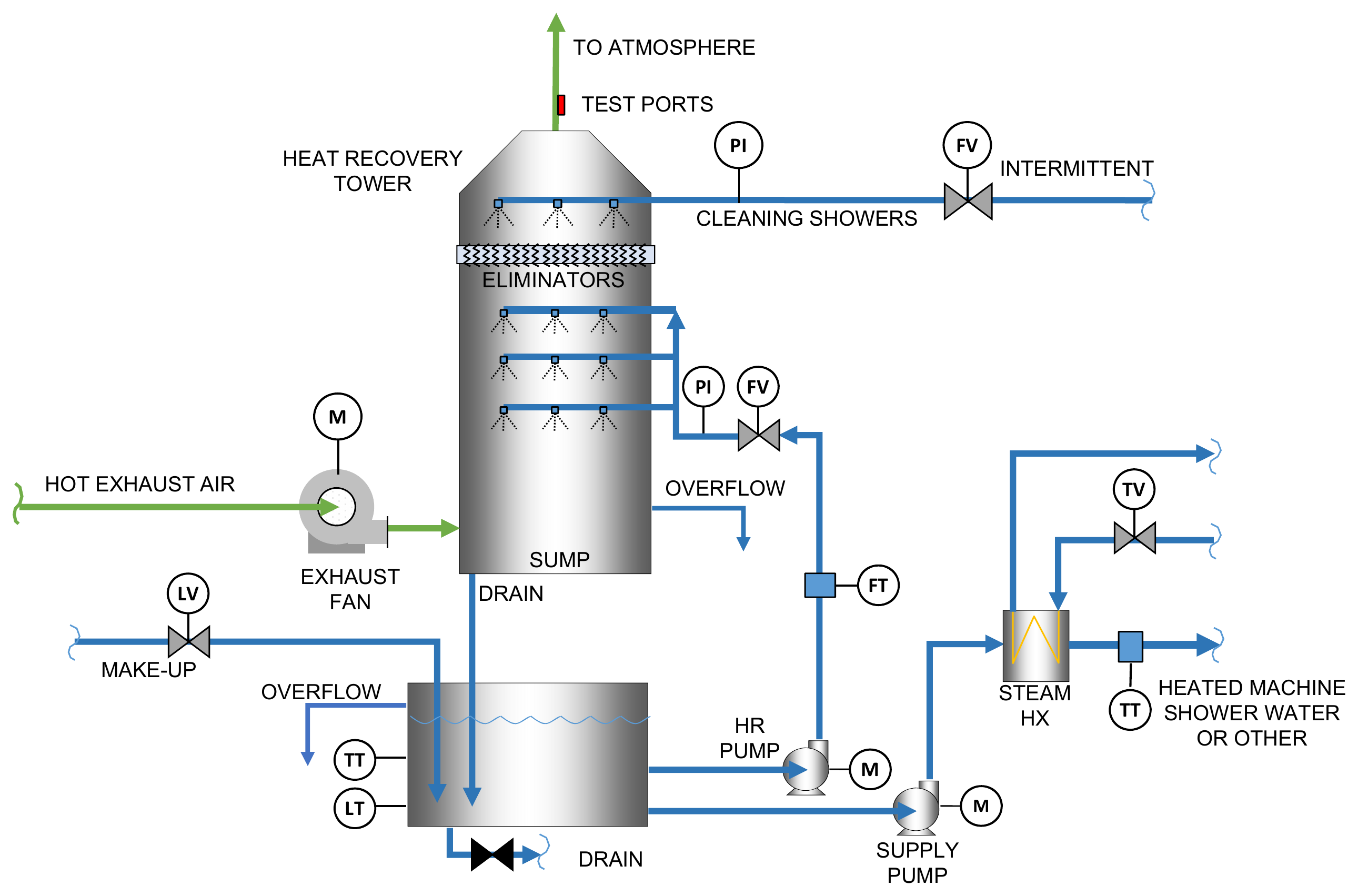
Follow the green line: the fan sends hot exhaust into the tower, where it rises through water sprays and then through droplet eliminators before discharge to atmosphere. The water absorbs heat by direct contact with the exhaust and drains from the tower sump into the tank below. One pump returns water to the sprays; a second sends it through a steam heat exchanger for additional heating before use as machine shower water or for another duty.
Mining applications
Warm process exhaust may carry heat that can serve another duty. In this arrangement, exhaust contacts circulating water in a recovery tower. The resulting water quality and temperature must suit its proposed use, because direct contact can transfer exhaust contaminants into the water.
A fan moves the assessed exhaust stream through the heat-recovery arrangement.
Circulating water contacts the exhaust and collects in the sump and reservoir.
Pumps supply warmed water to an appropriate process use. The source arrangement includes supplementary steam heating.
Eliminators separate entrained droplets before exhaust discharge. Make-up, overflow, drains, and cleaning provisions support operation.
| Component | Role in the system |
|---|---|
| Recovery tower ↗ | Provides the direct-contact heat-transfer section. |
| Exhaust fan ↗ | Moves the process exhaust through the arrangement. |
| Droplet eliminators ↗ | Separate entrained liquid ahead of the outlet. |
| Reservoir and pumps | Collect, circulate, and deliver recovery water. |
Linked components open the VentilationComponents.com supplier catalogue. Equipment selection forms part of the system engineering.
Before equipment selection
Tell us about the material, operating conditions and problem you need to address.