 PONKA
Industrial building HVAC
Outdoor air, filtration, heating, and cooling coordinated around the needs of a defined plant space.
ExploreVentilation & HVAC / PFD-01
Filtered, heated outdoor air to replace air removed by process exhaust and dust collection.
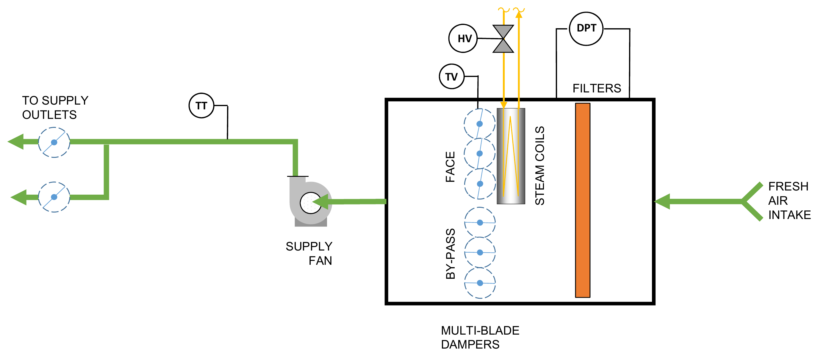
Read this drawing from right to left. Outdoor air enters through the filter; the face and bypass dampers set how much of it passes through the steam coils and how much flows around them. The supply fan sends the combined air to two outlets. The drawing also shows where filter pressure drop and supply-air temperature are measured.
Mining applications
When a processing building exhausts air, replacement air must enter somewhere. A dedicated make-up air unit introduces it through a planned intake and distribution system. Where steam is available, a steam coil provides heat before the air reaches the work area.
An intake and filter section admit air from a location selected away from exhaust discharge and dust sources.
Steam coils heat the air. Face and bypass dampers adjust how much air passes through the coil section.
The supply fan delivers air to outlets positioned to support the building air balance without disturbing extraction hoods.
Supply temperature and filter pressure measurements help operators track heating and filter condition.
| Component | Role in the system |
|---|---|
| Intake filter housing ↗ | Holds filtration selected for incoming airborne particulate. |
| Steam coil | Transfers heat from the steam service into the supply airstream. |
| Face and bypass dampers ↗ | Regulate airflow through and around the heating section. |
| Supply fan ↗ | Moves air through the unit and distribution ductwork. |
Linked components open the VentilationComponents.com supplier catalogue. Equipment selection forms part of the system engineering.
Before equipment selection
Tell us about the material, operating conditions and problem you need to address.